G.V.Lab.(Global Volunteer Laboratory)

And even more breakthroughs

Breakthrough Flow

We will explain the patented flow that further improves the performance of CO2 separation, concentration, and capture using the Wet-TSA method.
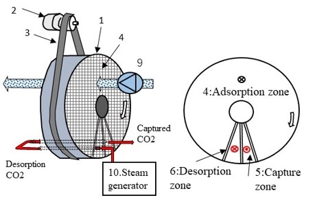
In the case of the rotor rotating type, the rotor is divided into an adsorption zone, capture zone, and desorption zone in the direction of rotation as shown in the figure, and the zones are sealed while the rotor rotates.
1. Air is passed through the adsorption zone to adsorb CO2.
2. When saturated steam at about 100°C is introduced into the desorption zone, the condensation heat of the saturated steam desorbs the CO2 adsorbed on the rotor.
3. The desorbed CO2 is passed through the capture zone and captured.
The secret benefit of this patented flow
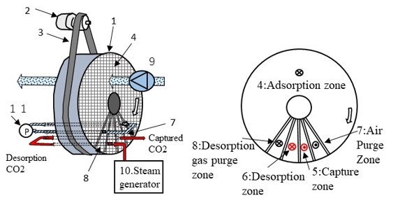
By passing the mixed gas of desorbed CO2 and steam through the capture zone at the front of the rotation direction,
① As the rotor rotates, gas in the rotor gaps and adsorbed oxygen are expelled in the capture zone, preventing oxygen from entering the desorption zone, which is the hottest, and thermal oxidation deterioration is avoided.
② The mixed gas at the outlet of the desorption zone still contains sufficient saturated steam, so it has the effect of preheating and heat recovery before the desorption zone.

A trick to further improve performance: Circulation purge method

Rotor rotation type
If the adsorbent is moved to the desorption zone to desorb the adsorbed CO2 after passing the treated air through the adsorbent, there is a high risk that the air present in the honeycomb voids will move and be mixed into the capture/desorption zone. Not only does the mixture of air reduce the purity of the captured gas concentration, but the adsorbent, which is prone to thermal oxidation degradation, will also be thermally oxidized and deteriorated when it comes into contact with oxygen at a high temperature.
The circulation purge zone is located in two places in the direction of the rotor rotation, one after the final stage of the treatment zone and one just before passing through the desorption zone and moving to the treatment zone. Both zones are connected, and gas is constantly circulated to exchange air and desorbed CO2. This action prevents air from moving to the capture/desorption zone, and at the same time prevents the desorbed CO2 gas from being exhausted to the adsorption zone. In other words, the circulation purge zone prevents air from mixing into the captured CO2 gas, and at the same time prevents the release loss of captured CO2 to the exhaust.
>BBBコースの詳細はこちら

Multi-stage recovery zones for even greater energy efficiency

The patent flow is based on the single-stage recovery zone mentioned above, but the recovery zone can be multi-staged to improve energy efficiency.
When separating, concentrating, and capturing CO2 from air, there is no need to increase the adsorption rate on the adsorption side more than necessary. This is because there is a lot of air, so it is sufficient to adsorb and exhaust only the amount that is easy to separate from the abundant air. Even if the adsorption rate decreases by narrowing the rotor width, it is more beneficial for the device to reduce pressure loss and reduce airflow energy. If the rotor width is reduced from 400 mm to 50 mm, which is one-eighth of the original width, the airflow energy will also be one-eighth, but since the CO2 adsorption rate is nearly 50%, it can be estimated that when the CO2 concentration of the passing air is 1000 ppm, the outlet CO2 concentration will be about 500 ppm. At this concentration, the CO2 concentration is only slightly higher than that of the outside air, so it is possible to reuse it as air conditioning supply.
On the other hand, to increase the energy efficiency of the CO2 capture device, it is desirable to have a high thermal efficiency on the desorption and recovery side, but narrowing the rotor width will reduce the thermal efficiency. Even if the desorption zone outlet gas is passed through a single-stage recovery zone, the outlet gas is still a mixed gas with a high temperature and a large amount of steam, so it must be cooled and dehumidified before the CO2 gas is compressed and liquefied.
Therefore, by setting up a multi-stage recovery zone as shown in the figure and passing the gas through multiple stages, the thermal efficiency of the recovered gas can be increased to the same level as that of a 150 mm wide rotor, even with a 50 mm rotor. By preheating the rotor, the thermal efficiency of the mixed gas passing through the multi-stage recovery zone is improved, improving energy efficiency. Since the recovered gas can be recovered after being reduced in temperature and humidity, the cooling and dehumidification load before compression and liquefaction is reduced, improving energy efficiency.
 

>CCCコースの詳細はこちら

About

PAGE TOP