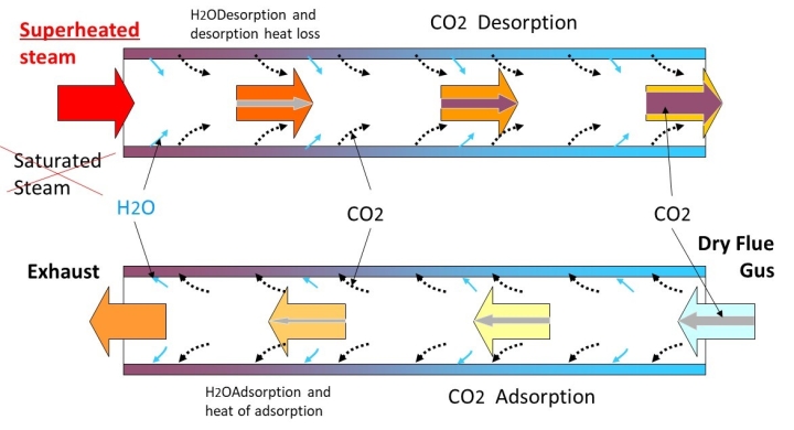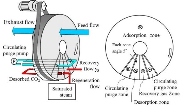
The Idea of Saturated Steam Regeneration: An Empty Theory?
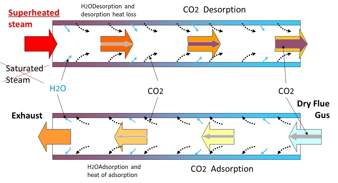
● The Idea of Saturated Steam Regeneration: An Empty Theory?
The basic idea for the Wet-TSA method was conceived in 2012 and presented at the final meeting with our research partner. However, perhaps because it was considered an empty theory, no one agreed with it, and I forgot about it for a while.
● Zeolite-Based TSA Method
At that time, as part of the company's next-generation product development goals, we were also working on improving the performance of CO2 concentration using zeolite rotors. We considered various new (complex) flows, including the addition of a dehumidifying rotor, but we realized there were limitations. My successors were also testing amine-based methods in parallel, but they only learned about the insurmountable limitations of thermal and oxidative degradation and the TSA method.
● Hot Water Regeneration
So, we also considered regeneration using hot water and even conducted tests using PET bottles, but this did not lead to any further ideas.
● Recalling Saturated Steam Regeneration
One day, as my retirement as an executive approached, I remembered saturated steam regeneration.
I proposed filing patent applications, but no one supported it, and the intellectual property department didn't seem likely to take action, so I completed 80-90% of the specifications myself and filed applications one after another.
●Then I retired from my executive position and became a contract employee.
I was educating younger colleagues to pass on my years of research experience in total heat exchangers and desiccant dehumidifiers. In between, I was quietly conducting prototype experiments in a corner, modifying discarded test equipment to implement the saturated steam regeneration idea I had previously patented, but it wasn't working. The recovery gas I wanted to cool wouldn't cool down properly, and conversely, the insulated equipment was insufficiently insulated, causing condensation of saturated steam and making everything wet.
●One year after becoming a contract employee, I was asked to become an auditor. I was given permission to continue the experiments for a while, but there was no budget, so I modified discarded equipment and used scrap materials from the factory to build experimental equipment - No. 3 to No. 1, and continued the experiments.
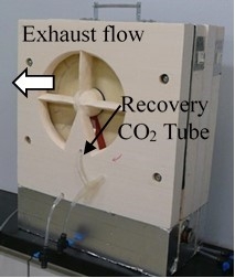
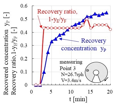
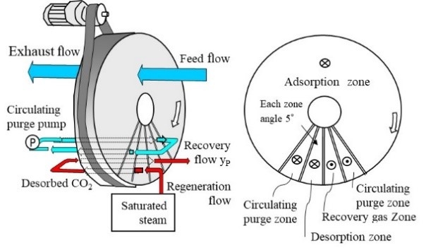
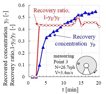
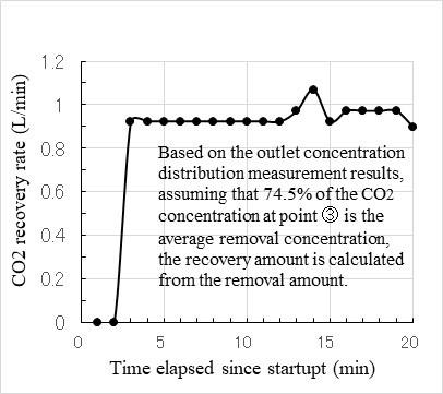
—The first unit was a small dehumidification test machine made of acrylic plate (for a φ320mm x 50mm rotor) that was prototyped more than 10 years ago and proved useless, which was secretly kept and decluttered, and was modified for use with DAC. We obtained some prototype rotor material for CO2 and assembled it into a φ320mm x 50mm rotor, and the method involves increasing the recovery CO2 concentration by introducing boiling steam into the desorption circulating gas. No matter how we changed the conditions, the maximum concentrated CO2 concentration we could achieve was about 3%. We thought this was due to the release of CO2 into the outside air due to the rotor rotation and the mixing of outside air into the CO2.