G.V.Lab.(Global Volunteer Laboratory)

Reducing CO2 emissions through the capture and use of green CO2.

Various CO2 capture methods are being considered, and pilot plant tests are also being conducted.

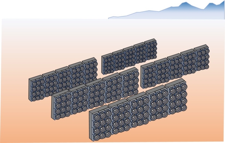
Various DAC CO2 capture methods are being considered, and pilot plants are being tested, but they require inexpensive heat sources and vast installation spaces, and are located far from urban areas. Therefore, it is more realistic to capture the CO2 and store it in CCS (carbon capture and storage) to sell carbon credits.
Large-scale DAC plant

.A solution that enables locally produced and consumed CCU in urban areas.

Human breath contains between 3% (30,000 ppm) and 9% (90,000 ppm) of CO2. The amount of CO2 emitted per person in 24 hours is estimated at approximately 1 kg, meaning that in a city of 1 million people, this translates to 1,000 tons of CO2 emitted per day.
The CO2 emitted from human breath is considered recycled green CO2 derived from food, and therefore does not contribute to global warming.
By capturing and utilizing this green CO2, we can increase CO2 emissions from transportation, impose a carbon tax on the sale of gray liquefied CO2 derived from fossil fuels, certify green CO2 as carbon credits, and invest in the cost transfer for the widespread adoption of green CO2, as well as in the development and promotion of gray CO2 reduction methods, thereby advancing measures against global warming.
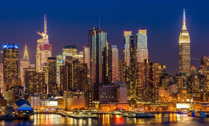
Major cities become green CO2 mines
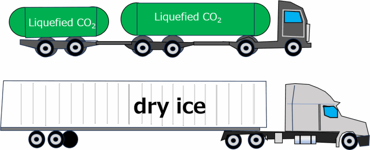
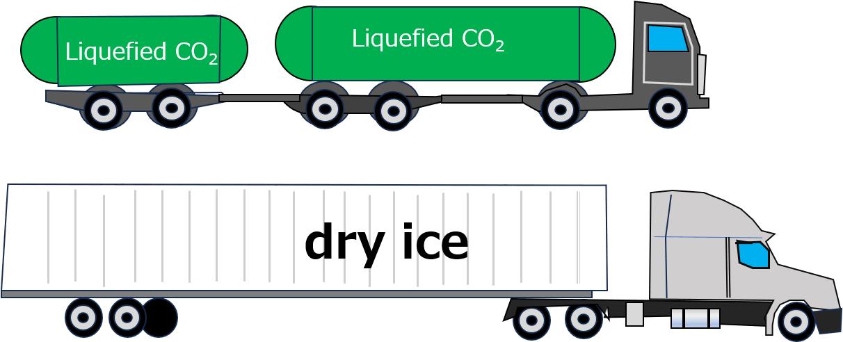
CO2 emissions from the transportation of liquefied CO2 and dry ice will also be eliminated.

The calculation basis for the establishment of a locally produced and consumed CCU through an urban DAC.

Assuming a New York-style high-rise office building:
• Number of floors: 50
• Exhaust airflow per floor: 10,000 m³/h
• CO₂ concentration in exhaust: 1100 ppm
• Recovery rate: 50%
① CO₂ emissions per floor: 1100 × 10⁻⁶ × 10,000 ≈ 11 m³/h (approximately 20 kg/h in mass)
② 50% recovery per floor: ≈ 10 kg/h/floor
③ Total for 50 floors: 10 kg/h × 50 ≈ 500 kg/h (approximately 0.5 t/h of CO₂ recovered per building).
On an annual basis, this translates to 0.5 t/h × 24 h/day × 365 days ≈ 4,380 t/year recovered.
Target buildings in New York: 100 buildings (high-rise office buildings and mixed-use buildings)
• Assuming 4,000 t recovered per building annually, 4,000 t/year × 100 ≈ 400,000 t/year. Theoretically, this allows for the production of approximately 400,000 tons of "urban DAC + dry ice/liquefied CO₂" annually within the New York metropolitan area alone.
The design allows for the creation of "CO₂ + dry ice self-sufficiency zones" in each city, supplied for urban logistics, freezing, medical, and food applications.
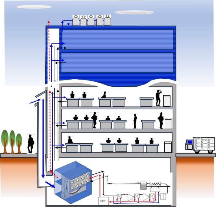
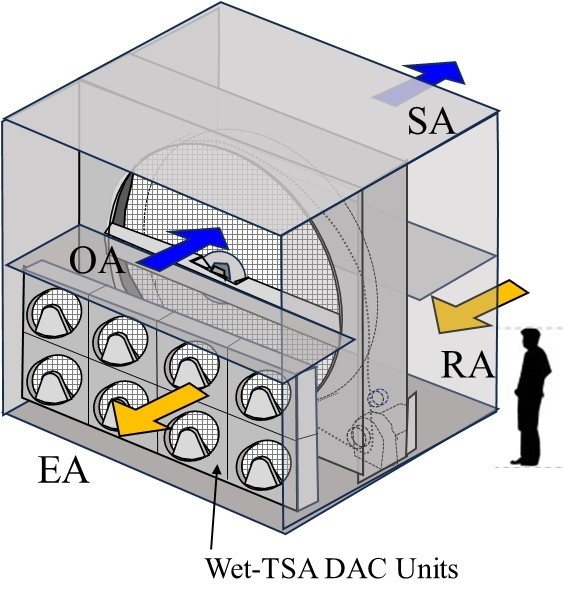
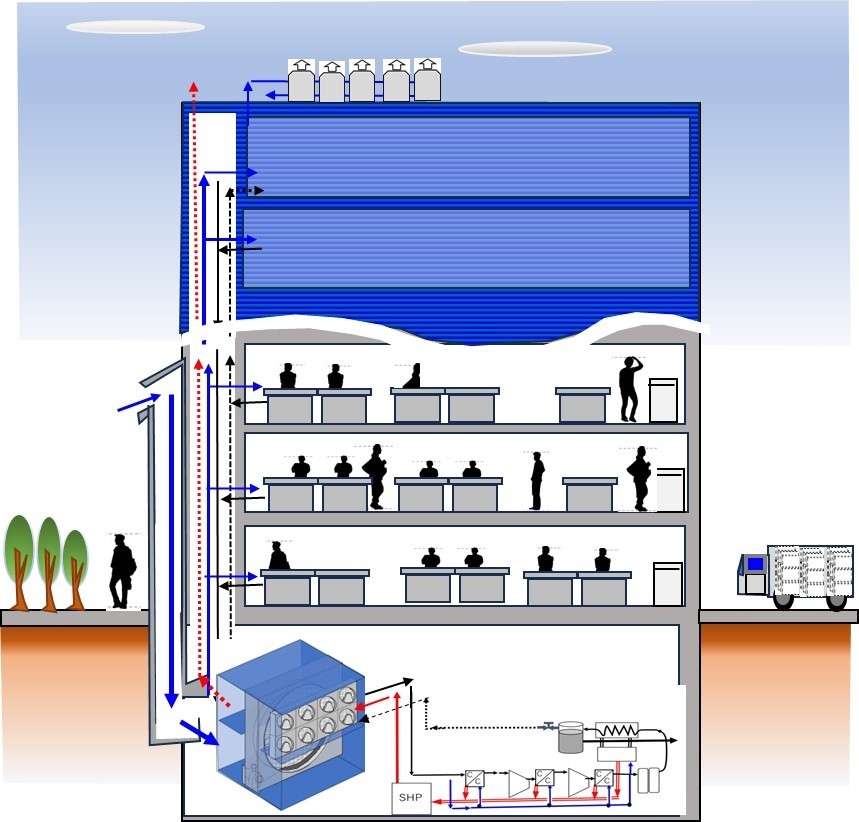
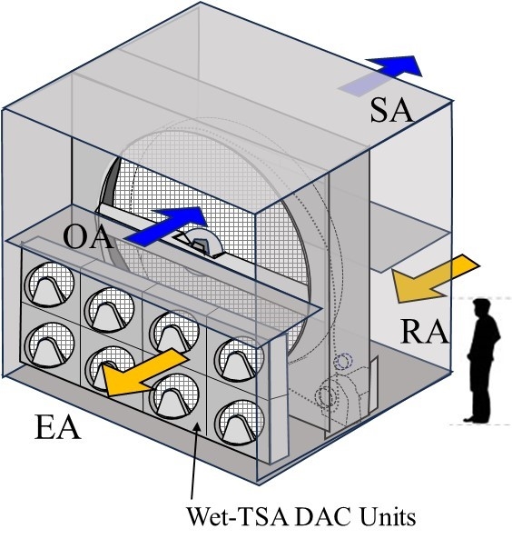
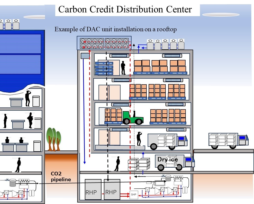
Multiple Wet-TSA miniature DACs are incorporated into the total heat exchanger installed in the basement of a high-rise building to recover CO2 from the air conditioning exhaust.
An example of a device incorporating multiple Wet-TSA miniature DACs into a total heat exchanger installed in the basement of a high-rise building.
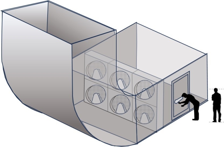
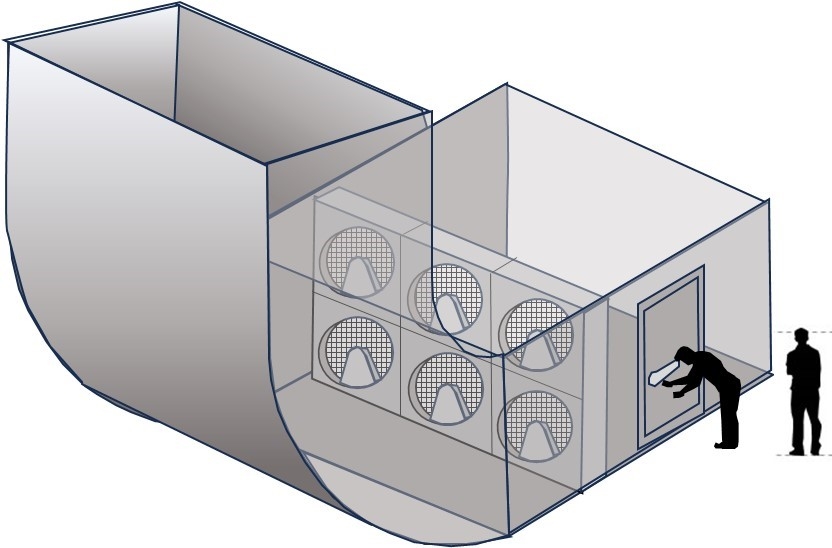
An example of incorporating multiple Wet-TSA miniature DACs into an exhaust duct.

Urban DAC + Logistics Hub Model

1. Suitability of Wet-TSA DAC for Urban Air Conditioning
• CO₂ Concentration: 900-1200 ppm (increase due to human activity) • Temperature: 24-30°C (air conditioning exhaust)
• Humidity: 40-60% (optimal for Wet-TSA) • Airflow: 5,000-20,000 m³/h per floor. In other words, the environment in which Wet-TSA operates most efficiently.
• Meaning of "1100 ppm × 50% recovery" (optimal point for energy and cost)
• 1100 ppm exhaust CO₂ amount: 1100 × 10⁻⁶ × 10,000 ≈ 11 m³/h. In terms of mass, approximately 20 kg/h (estimate).
• With a 50% recovery rate, this is approximately 10 kg/h/floor. For 10 floors, this is 100 kg/h; for 20 floors, it's 200 kg/h. This is a sufficient amount for an urban dry ice production facility.
• Wet-TSA counteracts sorbed heat through "evaporative cooling of a wet rotor," so with a 50% recovery rate, it can operate with almost no increase in air conditioning load.
2. Strengths of the underground liquefaction and dry ice production model
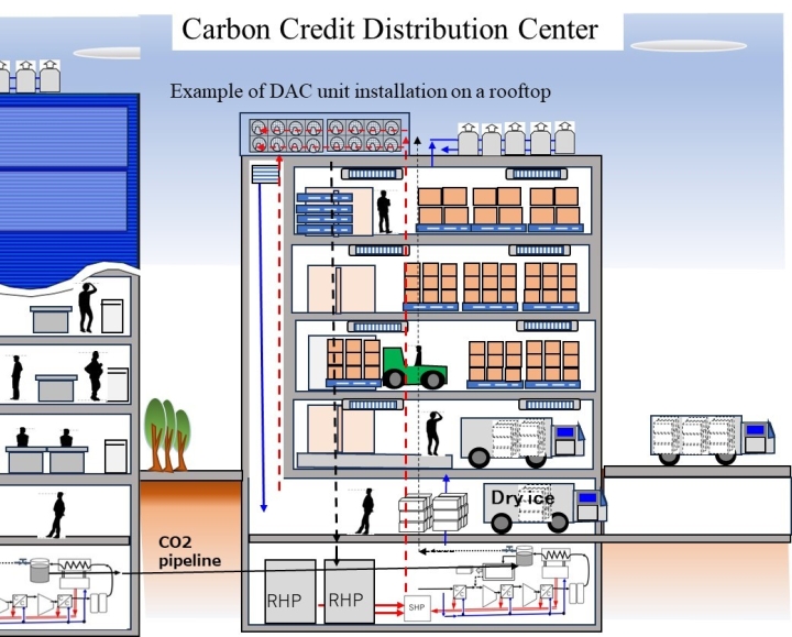
• Urban buildings are "natural CO₂ accumulation points" • CO₂ concentration naturally increases due to human activity • Exhaust ducts are already in place • Machine rooms, refrigeration equipment, and power supply are located underground • Easy access for logistics vehicles
• Advantages of underground liquefaction and dry ice production • Immediate response to dry ice demand within cities • Direct delivery to cold storage warehouses and distribution centers is possible • Solves dry ice shortages in summer • Reduces reliance on imported dry ice • Shorter CO₂ transport distance and reduced emissions The "waste heat recovery heat pump + saturated steam regeneration" patent No. 7174205 is perfectly compatible with the waste heat (air conditioning and refrigeration equipment) of urban buildings, enabling a highly energy-efficient urban CCU (Carbon Capture and Use Unit).
Urban DAC + Logistics Hub Model
Minimizing CO2 emissions from the transportation of liquefied CO2 and liquefied CO2 for dry ice.
Fuel costs for Frozen trucks are approximately 35% higher than those for regular trucks.
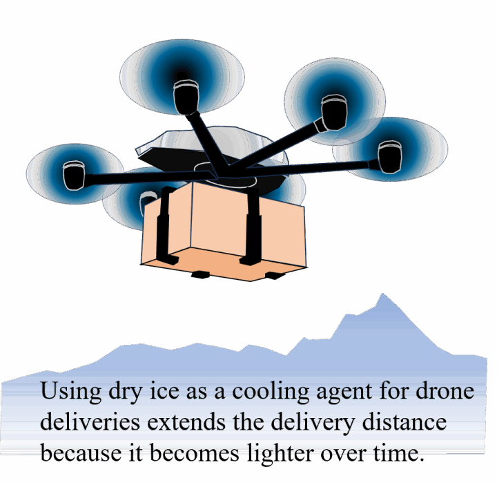
With the increasing number of small-package deliveries and drone deliveries, used ice packs become waste in unwanted packages.

About

PAGE TOP